Repower Project
Happy Ours came equipped with an OMC Saildrive. Unfortunately, OMC corporation introduced the OMC Saildrive about the time the marine industry made a decisive move toward diesel motors for sailboat auxiliaries in this class of boat. The OMC Saildrive was actually a very nice product and mine performed admirably. But with relatively few ever being produced, OMC apparently chose to not support it beyond what was required by law. Many parts are unavailable, period.
The ultimate demise for mine was corrosion of the lower unit gear casing. Initially, I feared that I had an electrolysis problem because the metal disappeared at an alarming rate.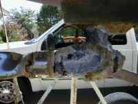
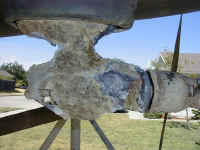
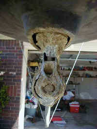 However, the gear case corroded away while the sacrificial zinc looked great, with no change. I replaced the zinc and ensured that it had good contact with the gear case, but the corrosion continued. I cannot say what the problem was with any certainty, but, after much research and discussions on on the internet, I believe that the problem was a punky metal alloy at manufacture. It is my understanding that many OMC outboards of the same vintage suffered the same fate.As you can see from these photos, (click on any of them for a larger version) the degree of corrosion was severe. I obviously had water instead of oil in the gear case. Amazingly, the thing was still shifting and pushing the boat at the time I pulled it out.
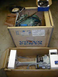
I had been aware for several years that a repower was going to be required. I periodically searched the internet for a suitable and cost effective solution. I made the decision to stay with a saildrive for the simplicity of installation. This made the search MUCH more difficult, but I eventually stumbled onto a 9 or 10 year old Volvo 2002HEBT diesel and Volvo 120S saildrive that had originally been purchased for a project that never got off the ground. It was still in the original shipping crate and was complete with the fiberglass motor mount. I purchased it for $3000 which was about 30% of current new price for similar equipment. ( I priced new equipment with Volvo, Yanmar, and Range,a Kubota product. All ran approximately $6000 for a motor and $3000 for a saildrive.) The Volvo was in Washington State and I am in Texas. With the help of a friend in the trucking business, I had the motor shipped frozen with food for $300 which was much cheaper that regular freight rates I was quoted. The Volvo sat in my garage for about one year before I started the project.
The OMC Saildrive mount was chopped and ground a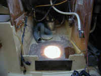 w
w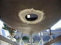 ay, leaving a sizeable hole in the hull. Unfortunately, this hole was in the wrong place for the new saildrive. The OMC unit had a vertical shaft motor on top of the drive unit and the Volvo is a horizontal shaft motor that sits in front of the saildrive unit. Therefore, the new saildrive had to be positioned about 10 inches aft of the old location. I removed fiberglass around the hole by grinding, tapering the thickness of the hull to paper thin at the edge of the hole. This taper spanned about 3 to 4 inches from the edge of the hole all around. Most of the grinding was done inside the hull, but a small taper was made on the outside also. This allowed progressively larger pieces of fiberglass cloth and mat to be applied, bringing the area back to original thickness. This is the proper way to glass in a hole for strength and to assure no cracks develop.
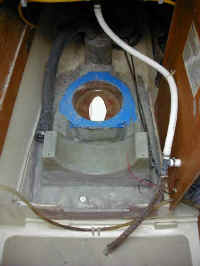 The fiberglass motor and saildrive mount was positioned with careful measuring to make sure that there would be no interferences once the motor was installed. The bottom of the mount had to be trimmed to fit the contour of the hull and to level the motor and drive unit. This was accomplished as follows: First the boat was leveled on both axis by adjusting the trailer it was sitting on with jacks and blocks. Next, the mount was leveled on both axis by shimming under the low points with small scraps of wood. I then scribed a line all around the mount that matched the contour of the hull. This was accomplished by taping a pencil stub to a short stick such that the height of the pencil lead matched the largest gap between the mount and the hull. I then simply dragged the pencil and stick around the mount, keeping the stick in contact with the hull at all times and allowing the pencil to mark a line on the mount. The mount was then removed and a belt sander with a very coarse grit belt was used to grind down to the scribed line. The mount was repositioned in the hull and matched the hull contour perfectly. The blue masking tape in the photo was applied to the saildrive gasket mating surface to keep it clean.
Glassing the mount in place was straightforward. I used West System epoxy with a combination of fiberglass cloth, mat, and woven roving. The woven roving is great for this application because it has the bulk of mat but us much stronger. I ordered the woven roving from Defender Industries. I used six layers of alternating roving and mat. The first layer was a layer of mat about two inches wide. I creased it down the middle so that about one inch was applied to both the mount and the hull. Successive layers were increasingly wider. This layering technique is similar to that used to fill in the large hole discussed earlier. The roving is somewhat coarse in texture. The alternating layers of mat helped smooth it out. My final layer was of thin fiberglass cloth with extra resin to end up with a very smooth surface for easy cleaning. Several layers were usually applied in one work session, so the glass work went fast. After the first application had set, I cut the new hole through the hull. The mount dictated where the new hole had to be located. The raw edges of the new hole were sealed with cloth and resin. The interior walls of the mount (around the hole) were glassed to the hull just like the outer walls of the mount.
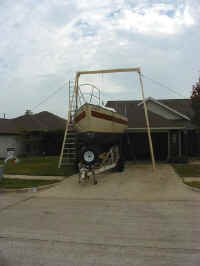 The 300 pound motor had to be lifted over the stern rail. A twenty foot tall wooden A-frame was erected, stabilized with rope. The A-frame was made inexpensively with 2x4 lumber legs and a 2x10 beam. Erecting the A-frame was the hard part. I fabricated the ends of the crossbeam such that the 2x4 legs could be inserted into sockets. The crossbeam was positioned on the ground in front of the boat, with one leg inserted at each end. Using a rop
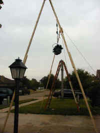 e attached to the middle of the beam, I raised the beam from the bow of the boat while two other people kept the bottom end of the two legs from sliding. Once the beam was at the top of the arc, the second leg for each end was inserted from the ground. The whole process was very tedious, but once erected and "staked" at each end with 50 foot ropes, it was very stable.
The boat was backed under the motor after it was hoisted. Once lowered into the companionway to a height just above the motor mount, the boat was pulled back forward until the hoist cable just touched the bottom of the companionway opening. At this point the motor only needed to move aft a few inches to be at final location. This process went smoothly and quickly.
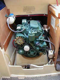 There were several other details like cleaning the tank and adding a return fuel line for the diesel, adding a raw water strainer, adding a primary fuel filter and water separator, etc. The raw water strainer can be seen mounted on the port side of the engine compartment near the back of the motor. The primary fuel filter can be seen mounted near the front of the motor. The coolant tank supplied with the motor was mounted high to starboard. It should be noted that I ordered the installation literature for this motor and it gave me installation requirements I was unaware of. For
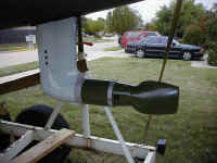 example, the coolant tank was to be mounted such that the normal fill level marked on the tank was at the same elevation as the top of the exhaust elbow. Also the rubber hose from the coolant tank must not have a low point between the tank and motor. These are small details and I don't know how important they were. I definitely would not have gotten these details right without the installation literature from Volvo. I completed the installation with a folding prop from Volvo. Overall, the project went smoothly.
Performance has met expectations. My only issue is that I may have put a prop on her with too little pitch. Volvo specified only one prop pitch for this motor, period. I called and discussed the fact that I was replacing a 15 horsepower motor with an 18 horsepower motor and suggested that with excess horsepower I might need to add pitch to load the motor properly. They "went by the book" and insisted the listed prop would be correct. I went with their specified prop. Well....... I now have about 0.2 knot less top speed than I did with the smaller motor. The Volvo has a governor and it is clearly limiting motor output, not the load. So, in retrospect, I believe I was right and should have put more prop under her. She does hull speed easily with power to spare.